Quiz 7 Answers
Each question as it appears in the Quiz 7 PDF, followed by the direct answer. For the full step-by-step work, follow the "Full solution" link under each answer.
Jump to: 1 · 2 · 3 · 4 · 5 · 6 · 7 · 8 · 9 · 10 · 11
Problem 1
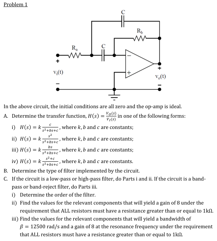
A. $$H(s)=k\frac{bs}{s^2+bs+c},\qquad k=-\frac{R_b}{2R_a},\quad b=\frac{2}{CR_b},\quad c=\frac{1}{C^2R_aR_b}$$
B. Band-pass filter
C (iii). $R_a=1$ kΩ, $R_b=16$ kΩ, $C=10$ nF
C (iii). $R_a=1$ kΩ, $R_b=16$ kΩ, $C=10$ nF
Problem 2
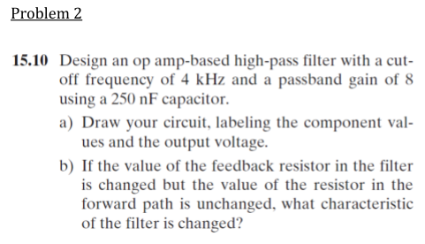
a) First-order high-pass (Fig 15.4): 250 nF in series with $R_1=159\ \Omega$ at the input, $R_2=1273\ \Omega$ in the feedback, $+$ input grounded.
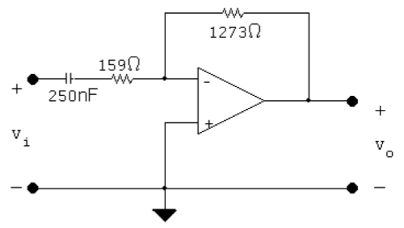 b) The passband gain changes; the cutoff frequency is unchanged.
Problem 3
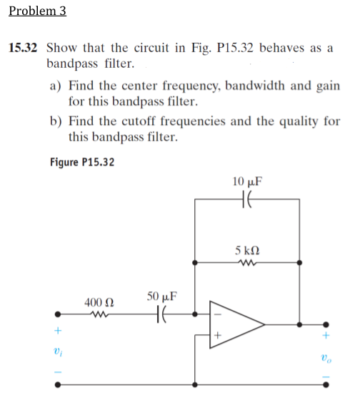
$$H(s)=\frac{-250s}{(s+50)(s+20)}=\frac{-250s}{s^2+70s+1000}=\frac{-3.57(70s)}{s^2+70s+(\sqrt{1000})^2}$$
a) $\omega_o=\sqrt{1000}=31.6$ rad/s, $\beta=70$ rad/s, $K=-3.57$
b) $\omega_{c1}=12.17$ rad/s, $\omega_{c2}=82.17$ rad/s, $Q=0.45$
b) $\omega_{c1}=12.17$ rad/s, $\omega_{c2}=82.17$ rad/s, $Q=0.45$
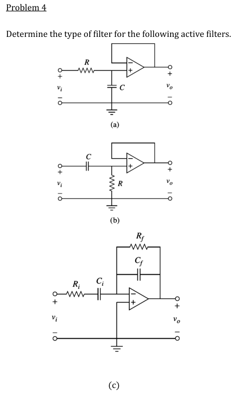
Problem 5
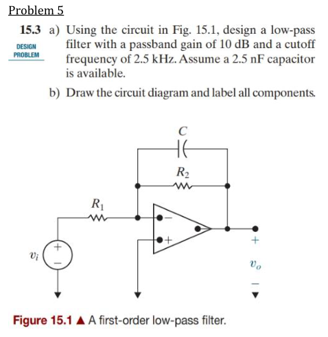
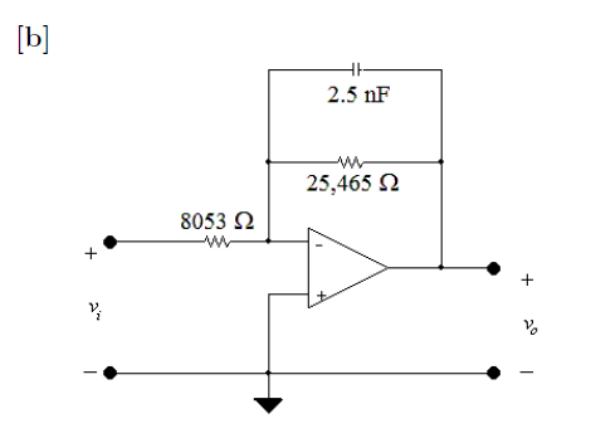
$R_1=8053\ \Omega$, $R_2=25{,}465\ \Omega$, $C=2.5$ nF (with $C$ in parallel with $R_2$ in the feedback).
Problem 6
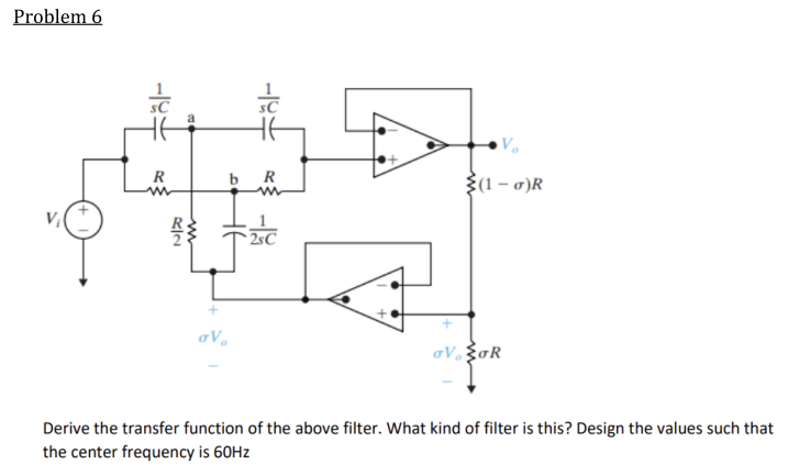
$$H(s)=\frac{s^2+\frac{1}{R^2C^2}}{s^2+\frac{4(1-\sigma)}{RC}s+\frac{1}{R^2C^2}}$$
Band-reject (notch) filter.
$\dfrac{1}{RC}=120\pi$, so $R=2.65$ kΩ and $C=1\ \mu$F.
$\dfrac{1}{RC}=120\pi$, so $R=2.65$ kΩ and $C=1\ \mu$F.
Problem 7
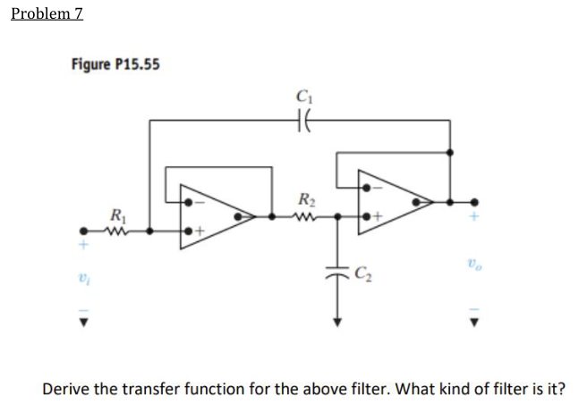
$$H(s)=\frac{\frac{1}{C_1C_2R_1R_2}}{s^2+\frac{1}{C_1R_1}s+\frac{1}{C_1C_2R_1R_2}}$$
Low-pass filter.
Problem 8
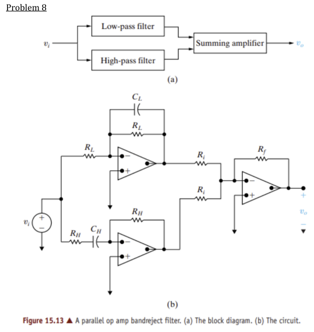
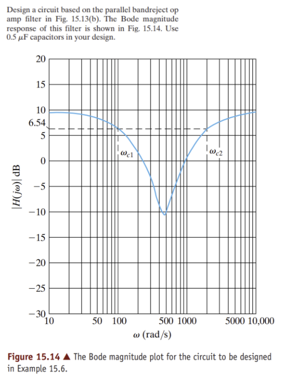
$R_L=20$ kΩ, $R_H=1$ kΩ, $R_i=1$ kΩ, $R_f=3$ kΩ (all capacitors 0.5 µF).
From the plot: $\omega_{c1}=100$ rad/s, $\omega_{c2}=2000$ rad/s, passband gain 3.
From the plot: $\omega_{c1}=100$ rad/s, $\omega_{c2}=2000$ rad/s, passband gain 3.
Problem 9
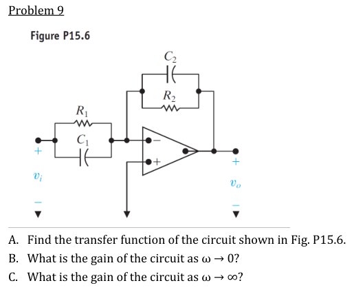
A. $$H(s)=-\frac{C_1}{C_2}\cdot\frac{s+\frac{1}{R_1C_1}}{s+\frac{1}{R_2C_2}}$$
B. $H(j0)=-\dfrac{R_2}{R_1}$ C. $H(j\infty)=-\dfrac{C_1}{C_2}$
Problem 10
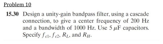
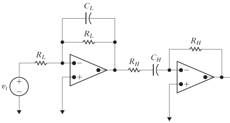
$f_{c1}=38.5$ Hz, $f_{c2}=1038.5$ Hz, $R_L=30.65\ \Omega$, $R_H=826.43\ \Omega$
Problem 11
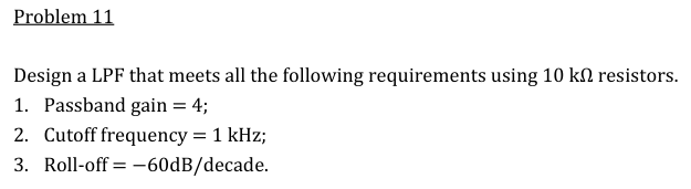
3rd-order Butterworth low-pass (−60 dB/dec means $n=3$, polynomial $(s+1)(s^2+s+1)$). All resistors 10 kΩ:
- Stage 1, first-order LPF (Fig 15.1): $R_1=R_2=10$ kΩ, $C=15.92$ nF
- Stage 2, 2nd-order cell (Fig 15.21): $R=10$ kΩ, $C_1=31.83$ nF (feedback), $C_2=7.96$ nF (to ground)
- Stage 3, inverting amp: $R_i=10$ kΩ, $R_f=40$ kΩ (four 10 kΩ in series), so the overall gain is $+4$