Quiz 7 Study Guide: Active Filters
EEL 3123C Linear Circuits II · Quiz 7 (labeled "Homework 6" in the PDF) · Textbook: Nilsson & Riedel, Chapter 15
This guide assumes you know nothing about filters yet. Read it top to bottom once. Section 0 is a map that names things like $H(s)$, $K$, $\beta$ and $Q$; don't worry about them yet, because every symbol is defined in §1 and explained in the sections after it. Yellow boxes are the equations and ideas you must memorize. Blue boxes explain why. Red boxes are traps.
0. What Quiz 7 asks you to do
Every problem on Quiz 7 is one of four jobs. Learn these four jobs and you can do the whole quiz:
- Derive $H(s)$: find the circuit's transfer function, usually with $H(s)=-Z_f/Z_i$ or with KCL.
- Identify the filter type (low-pass, high-pass, band-pass, band-reject) by checking what happens at very low and very high frequency.
- Read off the parameters (gain $K$, cutoff $\omega_c$, center $\omega_o$, bandwidth $\beta$, quality $Q$) by matching $H(s)$ to a standard form.
- Design: pick resistor and capacitor values that give the required numbers.
| Problem | Topic | Jobs | Guide section |
|---|---|---|---|
| 1 | Narrowband band-pass (op amp, two C's) | Derive, identify, design | §12, solution |
| 2 | First-order high-pass design (15.10) | Design | §8, solution |
| 3 | Band-pass from one op amp (15.32) | Derive, read off | §6, solution |
| 4 | Identify filter type from a picture | Identify | §7, solution |
| 5 | First-order low-pass design, gain in dB (15.3) | Design | §8, solution |
| 6 | Twin-T notch (band-reject) | Derive, identify, design | §12, solution |
| 7 | Two-buffer second-order low-pass (P15.55) | Derive, identify | solution |
| 8 | Parallel band-reject from a Bode plot (Ex. 15.6) | Read a plot, design | §10, solution |
| 9 | R‖C in and R‖C feedback (P15.6) | Derive, limits | solution |
| 10 | Cascade band-pass design (15.30) | Design | §10, solution |
| 11 | 3rd-order Butterworth low-pass design | Design | §11, solution |
How this connects to your earlier homework
- HW 1 (op amps): the ideal op amp rules in §5 are the same ones you used there.
- HW 2 to HW 4 (Laplace): you already know $s$, impedances in the $s$-domain and how to write a transfer function. Quiz 7 uses all three.
- HW 5 (passive filters): HW 5 used the same four standard forms ($k\frac{a}{s+a}$, $k\frac{s}{s+a}$, $k\frac{bs}{s^2+bs+c}$, $k\frac{s^2+c}{s^2+bs+c}$) with only R, L and C. Quiz 7 builds the same filters with op amps, which adds gain and keeps the load from changing the filter.
Contents
- Vocabulary: every symbol
- Impedance and the capacitor trick
- Transfer function, magnitude and dB
- The four filter types
- The op amp toolkit
- Standard forms: reading $K,\omega_o,\beta,Q$
- The $s\to0$ / $s\to\infty$ test
- First-order active LP and HP
- Scaling
- Broadband BP (cascade) and BR (parallel)
- Higher order and Butterworth
- Narrowband BP and twin-T notch
- Quiz 7 solved step by step
- One-page formula sheet and checklist
1. Vocabulary: every symbol you will see
| Symbol | Name | Meaning in plain words | Units |
|---|---|---|---|
| $v_i(t)$, $V_i(s)$ | input voltage | The signal you feed in. Lowercase $v(t)$ is in time; uppercase $V(s)$ is the same signal in the Laplace ($s$) domain. | V |
| $v_o(t)$, $V_o(s)$ | output voltage | What comes out of the filter. | V |
| $f$ | frequency | Cycles per second. | Hz |
| $\omega$ | angular frequency ("omega") | The same frequency in radians per second. $\omega = 2\pi f$. | rad/s |
| $s$ | Laplace variable | For steady sine waves, replace $s$ with $j\omega$. | 1/s |
| $j$ | imaginary unit | $j=\sqrt{-1}$ (engineers use $j$ because $i$ means current). So $j^2=-1$, which means $s^2=(j\omega)^2=-\omega^2$. | none |
| DC | direct current | Zero frequency: a constant signal. "DC gain" = $H(0)$, i.e. $s=0$. | |
| corner frequency | Where a filter's response bends; for $\frac{\cdots}{s^2+bs+c}$ it is $\sqrt c$. For a Butterworth filter it equals the cutoff. | rad/s | |
| Bode plot | A graph of gain in dB (up) against frequency on a log axis (right). On a log axis, each factor of 10 gets equal space, so the gridlines between 100 and 1000 are 200, 300, …, 900 and get closer together as you go right. | ||
| $Z$ | impedance | "Resistance" that can depend on frequency. $Z_i$ = input-side impedance, $Z_f$ = feedback impedance. | Ω |
| $H(s)$ | transfer function | $V_o(s)/V_i(s)$: what the circuit multiplies the input by. | none (V/V) |
| $|H(j\omega)|$ | magnitude / gain | How much a sine wave of frequency $\omega$ is scaled. | none, or dB |
| $K$ (or $k$) | passband gain | The gain in the frequencies the filter lets through. A negative sign only means the output is flipped (inverted). | none |
| $\omega_c$, $f_c$ | cutoff frequency | The edge of the passband: where the gain has dropped to $K/\sqrt2 \approx 0.707K$ (−3 dB). | rad/s, Hz |
| $\omega_{c1}$, $\omega_{c2}$ | lower / upper cutoff | The two edges of a band-pass or band-reject filter. $\omega_{c1}<\omega_{c2}$. | rad/s |
| $\omega_o$ | center (resonant) frequency | Middle of the band (peak of a band-pass, notch of a band-reject). | rad/s |
| $\beta$ | bandwidth ("beta") | Width of the band: $\beta=\omega_{c2}-\omega_{c1}$. | rad/s (or Hz) |
| $Q$ | quality factor | How narrow the band is: $Q=\omega_o/\beta$. Big $Q$ = narrow, sharp. | none |
| $n$ | order | Highest power of $s$ in the denominator. Sets how steeply the gain falls outside the passband. | none |
| $k_m$, $k_f$ | magnitude / frequency scale factor | Multipliers that convert a "prototype" design (1 Ω, 1 F, 1 rad/s) into real values. | none |
| $R$, $C$ | resistor, capacitor | Active filters here use only R, C and op amps (no inductors). | Ω, F |
| LPF, HPF, BPF, BRF | filter names | Low-pass, high-pass, band-pass, band-reject (also called "notch" or "bandstop"). |
2. Impedance and the capacitor trick
In the $s$-domain every component acts like a "resistance" called an impedance $Z$:
Combine impedances exactly like resistors:
Show the algebra for $R\parallel C$
Multiply top and bottom by $sC$: $$\frac{R\cdot\frac1{sC}}{R+\frac1{sC}}\cdot\frac{sC}{sC}=\frac{R}{sRC+1}.$$At very low frequency ($\omega\to0$): $Z_C=\frac1{sC}\to\infty$, so a capacitor is an open circuit (a break in the wire).
At very high frequency ($\omega\to\infty$): $Z_C\to0$, so a capacitor is a short circuit (a plain wire).
3. Transfer function, magnitude and decibels
To find out what happens to a sine wave of frequency $\omega$, put $s=j\omega$ and take the magnitude $|H(j\omega)|$. If the input amplitude is 1 V and $|H(j\omega)|=3$, the output amplitude is 3 V.
Magnitude of a fraction = (magnitude of top) / (magnitude of bottom), and $|a+jb|=\sqrt{a^2+b^2}$.
Decibels (dB) are a log way of writing gain:
| Linear gain | 1 | $1/\sqrt2\approx0.707$ | 2 | 3 | 3.162 | 10 | 100 |
|---|---|---|---|---|---|---|---|
| dB | 0 | −3 | 6.02 | 9.54 | 10 | 20 | 40 |
Check with the first-order LPF $H=K\frac{\omega_c}{s+\omega_c}$ at $s=j\omega_c$: $\;|H|=\frac{K\omega_c}{|j\omega_c+\omega_c|}=\frac{K}{|1+j|}=\frac{K}{\sqrt{1^2+1^2}}=\frac{K}{\sqrt2}$.
4. The four filter types
A filter lets some frequencies through (the passband) and blocks others (the stopband). The plots show gain (up) against frequency (right, log scale).
Passive vs. active. Passive filters (HW 5) use only R, L, C. Their gain can never exceed 1, and connecting a load changes their behavior. Active filters add an op amp, which gives two advantages:
- the passband gain can be greater than 1;
- the output does not change when you connect a load.
They also avoid bulky inductors.
5. The op amp toolkit
An op amp is a triangle with two inputs, $-$ (inverting) and $+$ (non-inverting), and one output. For this course it is always ideal:
Rule 1: No current flows into either input: $i_+ = i_- = 0$.
Rule 2: The two inputs are at the same voltage: $v_- = v_+$. If $+$ is grounded, then $v_- = 0$ (the "virtual ground").
The one formula that solves most of Quiz 7: the inverting amplifier
If the $+$ input is grounded, the input goes through impedance $Z_i$ into the $-$ input, and $Z_f$ connects the $-$ input to the output, then:
Why? (2-line derivation)
The $-$ input sits at 0 V (Rule 2). The current entering through $Z_i$ is $\frac{V_i-0}{Z_i}$. It cannot enter the op amp (Rule 1), so it all flows through $Z_f$: $\frac{V_i}{Z_i}=\frac{0-V_o}{Z_f}$. Rearrange: $\frac{V_o}{V_i}=-\frac{Z_f}{Z_i}$.| Other op amp blocks | Gain | Used for |
|---|---|---|
| Inverting amp with resistors $R_i$, $R_f$ | $-R_f/R_i$ | Adding gain to a filter |
| Voltage follower (buffer): output wired to $-$, signal into $+$ | $+1$, so $V_o = V_+$ | Copies a voltage without loading it (Problems 4a, 4b, 6, 7) |
| Inverting summing amp: inputs $V_1, V_2$ each through $R_i$, feedback $R_f$ | $V_o=-\frac{R_f}{R_i}(V_1+V_2)$ | Parallel band-reject (Problem 8) |
| Non-inverting amp | $1+R_f/R_i$ | Positive gain |
When a circuit is not a plain inverting amp (for example Problems 1, 6, 7), use KCL (Kirchhoff's current law: currents leaving a node add to zero) at each unknown node, along with the two golden rules.
6. Standard forms: how to read $K$, $\omega_c$, $\omega_o$, $\beta$, $Q$
Every answer key writes $H(s)$ in one of these shapes. Your job is to rearrange your $H(s)$ until it looks exactly like one, then read the constants.
| Type | Standard form | What the letters mean |
|---|---|---|
| 1st-order LPF | $H(s)=K\dfrac{\omega_c}{s+\omega_c}$ | $K$ = gain at DC, $\omega_c$ = cutoff |
| 1st-order HPF | $H(s)=K\dfrac{s}{s+\omega_c}$ | $K$ = gain at high freq, $\omega_c$ = cutoff |
| 2nd-order LPF | $H(s)=k\dfrac{c}{s^2+bs+c}$ | $k$ = DC gain, $\sqrt c$ = corner freq |
| 2nd-order HPF | $H(s)=k\dfrac{s^2}{s^2+bs+c}$ | $k$ = high-freq gain, $\sqrt c$ = corner freq |
| Band-pass | $H(s)=k\dfrac{bs}{s^2+bs+c}$ | $k$ = gain at $\omega_o$, $\beta=b$, $\omega_o=\sqrt c$ |
| Band-reject | $H(s)=k\dfrac{s^2+c}{s^2+bs+c}$ | $k$ = passband gain, $\beta=b$, $\omega_o=\sqrt c$ |
The recipe for reading constants:
- Make the $s^2$ term in the denominator have coefficient 1. Divide top and bottom if needed.
- Denominator is now $s^2+bs+c$. Read $b$ and $c$.
- For a band-pass, rewrite the numerator as (number)$\times bs$. The number in front is $k$. Example: $\dfrac{-250s}{s^2+70s+1000}=\dfrac{-250}{70}\cdot\dfrac{70s}{s^2+70s+1000}$, so $k=-3.57$.
7. The $s\to0$ / $s\to\infty$ test: identify any filter
| $|H|$ as $s\to0$ | $|H|$ as $s\to\infty$ | Type |
|---|---|---|
| nonzero | 0 | Low-pass |
| 0 | nonzero | High-pass |
| 0 | 0 | Band-pass |
| nonzero | nonzero (and a dip in between) | Band-reject |
Two ways to do it:
- From the equation: plug in $s=0$, then keep only the highest powers of $s$ for $s\to\infty$.
- From the picture (faster): redraw the circuit twice. Low-frequency picture: every capacitor becomes an open. High-frequency picture: every capacitor becomes a wire. Then see whether any signal reaches the output.
8. First-order active low-pass and high-pass filters
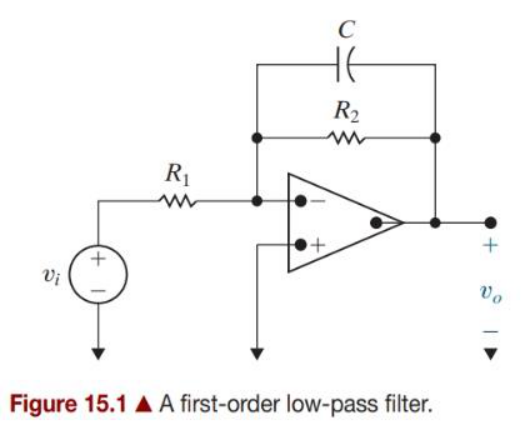
Fig 15.1: LPF. $R_1$ in, $R_2\parallel C$ in the feedback
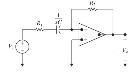
Fig 15.4: HPF. $R_1$ + $C$ in series at the input, $R_2$ in the feedback
Low-pass derivation: $Z_i=R_1$, $Z_f=R_2\parallel C=\frac{R_2}{1+sR_2C}$:
$$H(s)=-\frac{Z_f}{Z_i}=-\frac{R_2}{R_1}\cdot\frac{1}{1+sR_2C}$$To get the standard form, divide top and bottom of $\frac{1}{1+sR_2C}$ by $R_2C$:
$$H(s)=-\frac{R_2}{R_1}\cdot\frac{1/R_2C}{s+1/R_2C}$$High-pass derivation: $Z_i=R_1+\frac1{sC}=\frac{1+sR_1C}{sC}$, $Z_f=R_2$:
$$H(s)=-\frac{R_2}{Z_i}=-\frac{R_2\,sC}{1+sR_1C}$$Divide top and bottom by $R_1C$: the top becomes $\frac{R_2}{R_1}s$ and the bottom $s+\frac{1}{R_1C}$:
$$H(s)=-\frac{R_2}{R_1}\cdot\frac{s}{s+1/R_1C}$$| Transfer function | Gain | Cutoff | |
|---|---|---|---|
| LPF (Fig 15.1) | $H(s)=-K\dfrac{\omega_c}{s+\omega_c}$ | $\boxed{K=\dfrac{R_2}{R_1}}$ | $\boxed{\omega_c=\dfrac{1}{R_2C}}$ (C is with $R_2$) |
| HPF (Fig 15.4) | $H(s)=-K\dfrac{s}{s+\omega_c}$ | $\boxed{K=\dfrac{R_2}{R_1}}$ | $\boxed{\omega_c=\dfrac{1}{R_1C}}$ (C is with $R_1$) |
Design recipe (given $f_c$, gain, and $C$):
- Convert: $\omega_c=2\pi f_c$. If the gain is in dB: $K=10^{\text{dB}/20}$.
- Solve the cutoff formula for the resistor that touches $C$: LPF $R_2=\frac{1}{\omega_cC}$, HPF $R_1=\frac{1}{\omega_cC}$.
- Get the other resistor from $K=R_2/R_1$.
9. Scaling: from "prototype" to real parts
Textbook designs start from a prototype: all resistors 1 Ω, all capacitors 1 F, cutoff 1 rad/s. Those values are unrealistic, so you scale them:
How to pick them: $k_f$ comes from the frequency you need. Then choose $k_m$ so one given part comes out right:
- If you are told the resistor (say 10 kΩ) and the prototype resistor is 1 Ω: $k_m = 10{,}000$. (In general $k_m=R'/R$. The narrowband prototype in §12 has resistors that aren't 1 Ω, so there use the capacitor rule below.)
- If you are told the capacitor $C'$: $k_m = \dfrac{1}{k_f C'}$ (starting from a 1 F prototype).
10. Broadband band-pass (cascade) and band-reject (parallel)
Band-pass = low-pass THEN high-pass (in series, "cascade")
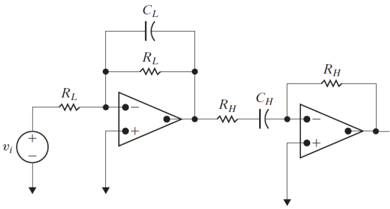
The signal must survive both filters. The LPF removes everything above $\omega_{c2}$, and the HPF removes everything below $\omega_{c1}$. What is left is the band between them.
Works only if broadband: $\omega_{c2}\gg\omega_{c1}$ (roughly $Q<\tfrac12$).
When given $\omega_o$ and $\beta$ instead of the cutoffs, solve the pair $\omega_{c1}\omega_{c2}=\omega_o^2$ and $\omega_{c2}-\omega_{c1}=\beta$. This gives the boxed $\omega_{c1,2}$ formulas from §6.
Show how (quadratic formula)
From the second equation, $\omega_{c2}=\omega_{c1}+\beta$. Substitute into the first: $\omega_{c1}(\omega_{c1}+\beta)=\omega_o^2$, i.e. $$\omega_{c1}^2+\beta\,\omega_{c1}-\omega_o^2=0$$ Quadratic formula, keeping the positive root (frequencies are positive): $$\omega_{c1}=\frac{-\beta+\sqrt{\beta^2+4\omega_o^2}}{2}=-\frac\beta2+\sqrt{\left(\tfrac\beta2\right)^2+\omega_o^2},\qquad \omega_{c2}=\omega_{c1}+\beta=\frac\beta2+\sqrt{\left(\tfrac\beta2\right)^2+\omega_o^2}$$Band-reject = low-pass AND high-pass side by side, then added (parallel)
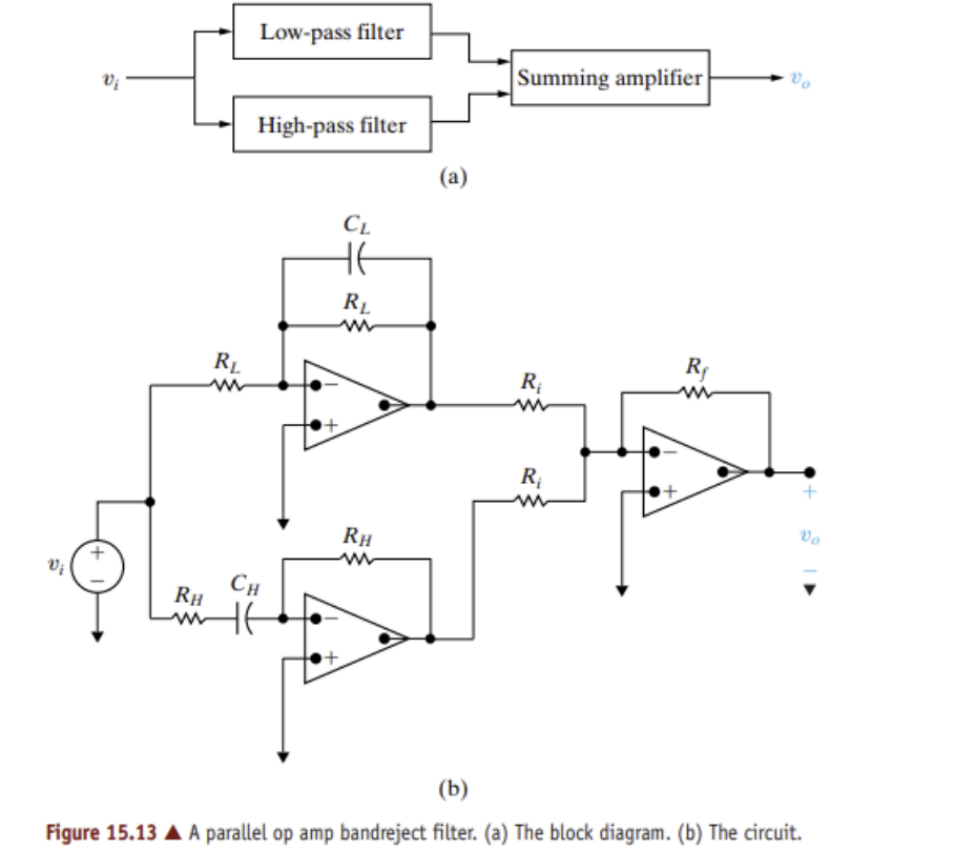
The LPF keeps lows, the HPF keeps highs, and the summing amp adds them. Frequencies in the middle are dropped by both, which leaves a notch.
11. Higher-order filters and Butterworth
A first-order filter falls off slowly. Higher order means a steeper fall-off:
Simply cascading $n$ identical first-order stages makes the corner droopy and moves the cutoff. A Butterworth filter picks the stages so the passband is as flat as possible and the cutoff stays exactly at $\omega_c$:
$$|H(j\omega)|=\frac{1}{\sqrt{1+(\omega/\omega_c)^{2n}}}$$| $n$ | Denominator |
|---|---|
| 1 | $(s+1)$ |
| 2 | $(s^2+\sqrt2\,s+1)=(s^2+1.414s+1)$ |
| 3 | $(s+1)(s^2+s+1)$ |
| 4 | $(s^2+0.765s+1)(s^2+1.848s+1)$ |
For a real cutoff $\omega_c$, replace $s$ with $s/\omega_c$ and clear the fractions. Example, $n=2$: $\;s^2+\sqrt2\,\omega_c s+\omega_c^2$. If you see a denominator with $b=\sqrt2\sqrt c$, it is a 2nd-order Butterworth.
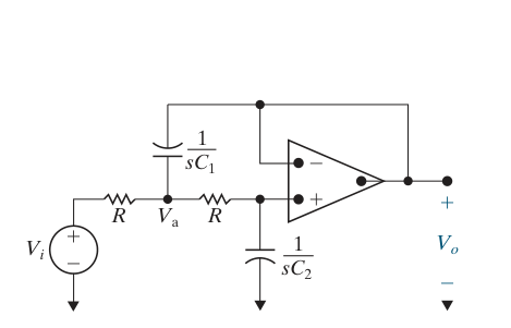
Fig 15.21: 2nd-order LP cell (R = 1 Ω)
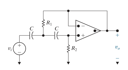
Fig 15.25: 2nd-order HP cell (C = 1 F)
The LP cell (Fig 15.21) has, with $R=1\,\Omega$ (derived in the textbook with KCL at $V_a$ and at the $+$ input; given, memorize the result):
$$H(s)=\frac{1/(C_1C_2)}{s^2+\frac{2}{C_1}s+\frac{1}{C_1C_2}}$$To make it equal $\dfrac{1}{s^2+b_1s+1}$, match coefficients:
Signs: these cells are built around a voltage follower (output wired to $-$), so their gain is $+1$ and they don't flip the signal. Inverting stages (Fig 15.1, Fig 15.4, the inverting gain stage) each contribute a $-1$. Multiply the signs of all stages to get the overall sign.
Butterworth design recipe (low-pass):
- Find the order $n$ from the roll-off ($-20n$ dB/dec) or from the stopband formula below.
- Look up the polynomial; split into $(s+1)$ and $(s^2+b_1s+1)$ factors.
- Each $(s+1)$ → prototype first-order LPF (1 Ω, 1 Ω, 1 F). Each $(s^2+b_1s+1)$ → LP cell with $C_1=2/b_1$, $C_2=1/C_1$.
- Scale: $k_f=\omega_c$ (in rad/s), $k_m$ from the required R or C.
- Need gain $\ne1$? Add an inverting amplifier stage with $R_f/R_i=$ gain.
Finding the order from a stopband spec (Eq. 15.15 and 15.16)
Spec: gain must be at least $A_p$ dB at $\omega_p$ (passband edge) and at most $A_s$ dB at $\omega_s$ (stopband edge). Both $A$'s are negative numbers. $$\sigma_p=\sqrt{10^{-0.1A_p}-1},\quad \sigma_s=\sqrt{10^{-0.1A_s}-1},\quad n=\frac{\log_{10}(\sigma_s/\sigma_p)}{\log_{10}(\omega_s/\omega_p)}$$ If $A_p=-3$ dB (so $\sigma_p\approx1$): $\;n\approx\dfrac{-0.05\,A_s}{\log_{10}(\omega_s/\omega_p)}$. Always round up to the next whole number.12. Narrowband (high-Q) band-pass and the twin-T notch
The cascade/parallel tricks only work when the band is wide. For a narrow band ($Q$ large) use these single-op-amp circuits.
Narrowband band-pass (Fig 15.27)
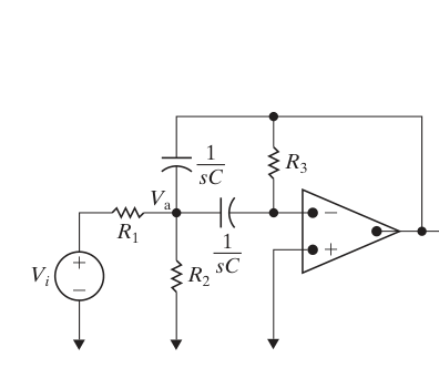
$H(s)$ comes from KCL at $V_a$ and at the $-$ input, the same method as Quiz Problem 1. Given, memorize.
Twin-T notch (band-reject), Fig 15.30, Quiz Problem 6
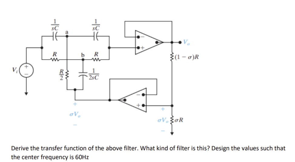
The "twin T" is two T-shaped networks side by side:
- two capacitors $C$ with an $R/2$ leg down the middle;
- two resistors $R$ with a $2C$ leg down the middle.
The middle legs return to $\sigma V_o$, a fraction of the output made by the $(1-\sigma)R$ / $\sigma R$ voltage divider and buffered by the lower op amp.
13. Quiz 7 solved step by step
Try each problem yourself first, then open the steps.
Problem 1 narrowband BP
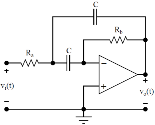
Asked: (A) $H(s)=V_o/V_i$ in one of the four forms. (B) Filter type. (C) Pick $R_a$, $R_b$, $C$ so that $\beta=12{,}500$ rad/s and gain = 8 at resonance, with every resistor ≥ 1 kΩ.
Know first: golden rules, KCL, the band-pass form $k\frac{bs}{s^2+bs+c}$.
Step 1: Label nodes
Call the junction of $R_a$ and the two capacitors node $A$ (voltage $V_a$). The $-$ input is at 0 V because $+$ is grounded (Rule 2). This is not a plain inverting amp, because node A has a third branch (the top C to $V_o$). So use KCL.
Step 2: KCL at the $-$ input
Current arrives from $A$ through the lower $C$ and leaves through $R_b$ to $V_o$. No current enters the op amp:
$$(V_a-0)\,sC=\frac{0-V_o}{R_b}\;\Rightarrow\; V_a=-\frac{V_o}{sCR_b}$$Step 3: KCL at node A
Sum of currents leaving A = 0 (to $V_i$ through $R_a$, to the $-$ input through C, to $V_o$ through the top C):
$$\frac{V_a-V_i}{R_a}+V_a\,sC+(V_a-V_o)\,sC=0$$ Multiply by $R_a$: $V_a(1+2sCR_a)-sCR_aV_o=V_i$.Step 4: Substitute and solve
$$-\frac{V_o}{sCR_b}(1+2sCR_a)-sCR_aV_o=V_i$$ Multiply through by $sCR_b$: $$-V_o\left[1+2sCR_a+s^2C^2R_aR_b\right]=sCR_b\,V_i$$ $$H(s)=\frac{-sCR_b}{s^2C^2R_aR_b+2sCR_a+1}$$ Divide top and bottom by $C^2R_aR_b$ so the $s^2$ coefficient is 1: $$H(s)=\frac{-\frac{1}{CR_a}s}{s^2+\frac{2}{CR_b}s+\frac{1}{C^2R_aR_b}}$$Step 5: Match to $k\dfrac{bs}{s^2+bs+c}$
$b=\dfrac{2}{CR_b}$, $c=\dfrac{1}{C^2R_aR_b}$. The numerator must equal $k\cdot b\cdot s$: $\;k\cdot\dfrac{2}{CR_b}=-\dfrac{1}{CR_a}\Rightarrow k=-\dfrac{R_b}{2R_a}$.Step 6: Type
$s\to0$: numerator → 0, so $H\to0$. $s\to\infty$: $\sim\frac{s}{s^2}\to0$. Zero at both ends → band-pass. (Picture check: at DC both caps open, so nothing reaches the op amp. At high frequency the top cap shorts the output to node A, and the lower cap shorts A to virtual ground, so $V_o=0$.)Step 7: Design
Gain at resonance = $|k|$ = 8: $\frac{R_b}{2R_a}=8\Rightarrow R_b=16R_a$.
Bandwidth: $\beta=b=\frac{2}{CR_b}=12{,}500$.
That is 2 equations and 3 unknowns, so you get to choose one. Pick the smallest allowed resistor: $R_a=1\text{ k}\Omega$. Then $R_b=16\text{ k}\Omega$ and
$$C=\frac{2}{\beta R_b}=\frac{2}{12{,}500\times16{,}000}=10\text{ nF}$$(Bonus check: $\omega_o=\frac{1}{C\sqrt{R_aR_b}}=25{,}000$ rad/s, $Q=\omega_o/\beta=2$.)
Problem 2 (15.10) 1st-order HPF design
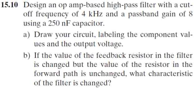
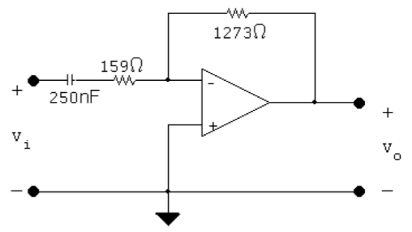
Asked: design a HPF with $f_c=4$ kHz, gain 8, $C=250$ nF. Then: what changes if only the feedback resistor changes?
Steps
- Use Fig 15.4: $\omega_c=\frac1{R_1C}$, $K=\frac{R_2}{R_1}$.
- $\omega_c=2\pi(4000)=25{,}133$ rad/s.
- $R_1=\dfrac{1}{\omega_cC}=\dfrac{1}{25{,}133\times250\times10^{-9}}=159.2\ \Omega$
- $R_2=K R_1=8\times159.2=1273\ \Omega$
- (b) The feedback resistor is $R_2$, which appears only in $K$. So the passband gain changes and the cutoff frequency stays the same.
Problem 3 (15.32) BP from one op amp
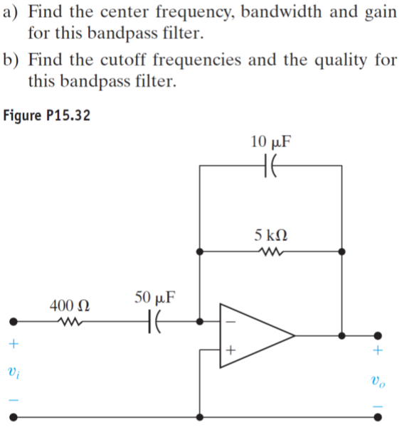
Asked: show it is band-pass. Find $\omega_o$, $\beta$, gain $K$, the cutoffs and $Q$.
Step 1: Impedances
$Z_i=400+\frac{1}{s(50\mu)}=\frac{1+0.02s}{s(50\times10^{-6})}$ (since $R_1C_1=400\times50\mu=0.02$).$Z_f=5000\parallel10\mu\text{F}=\frac{5000}{1+0.05s}$ (since $R_2C_2=5000\times10\mu=0.05$).
Step 2: $H=-Z_f/Z_i$
$$H(s)=-\frac{5000}{1+0.05s}\cdot\frac{50\times10^{-6}s}{1+0.02s}=\frac{-0.25s}{(1+0.05s)(1+0.02s)}$$ Factor: $1+0.05s=0.05(s+20)$ and $1+0.02s=0.02(s+50)$, and $0.05\times0.02=0.001$: $$H(s)=\frac{-250s}{(s+20)(s+50)}=\frac{-250s}{s^2+70s+1000}$$Step 3: Read off
$c=1000\Rightarrow\omega_o=\sqrt{1000}=31.6$ rad/s. $\;b=\beta=70$ rad/s.$k$: $-250s=k(70s)\Rightarrow k=-3.57$.
$Q=31.6/70=0.45$.
$\omega_{c1,2}=\mp35+\sqrt{35^2+1000}=\mp35+47.17$, so $\omega_{c1}=12.17$ and $\omega_{c2}=82.17$ rad/s.
Problem 4 identify type
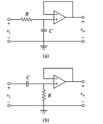
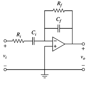
Steps (capacitor trick)
(a) R in series, C to ground, then a follower. Low $f$: C open, so $v_o=v_i$ (passes). High $f$: C shorts the node to ground, so $v_o=0$. → LPF.
(b) C in series, R to ground. Low $f$: C open, so nothing gets through. High $f$: C is a wire, so $v_o=v_i$. → HPF.
(c) Low $f$: $C_i$ open, so no input current and $v_o=0$. High $f$: $C_f$ shorts output to the $-$ input (0 V), so $v_o=0$. Zero at both ends → BPF. (Problem 3 is this same circuit with numbers.)
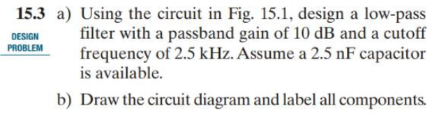
Problem 5 (15.3) 1st-order LPF, dB gain
Steps
- Fig 15.1: $\omega_c=\frac1{R_2C}$, $K=\frac{R_2}{R_1}$.
- Gain in dB → linear: $K=10^{10/20}=3.162$.
- $\omega_c=2\pi(2500)=15{,}708$ rad/s.
- $R_2=\dfrac{1}{\omega_cC}=\dfrac{1}{15{,}708\times2.5\times10^{-9}}=25{,}465\ \Omega$
- $R_1=\dfrac{R_2}{K}=\dfrac{25{,}465}{3.162}=8053\ \Omega$
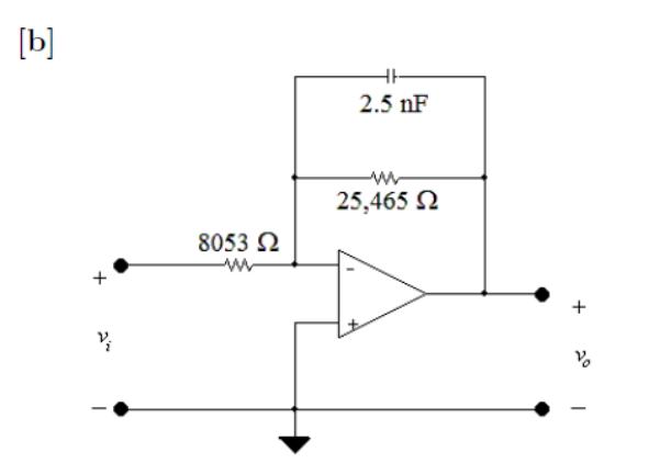
Problem 6 twin-T notch
Asked: derive $H(s)$, name the filter, and design for a 60 Hz center frequency.
Read the picture:
- The top op amp is a follower, so its $+$ input sits at $V_o$.
- The bottom op amp is a follower of the divider output, so the bottom "ground" of the twin-T sits at $\sigma V_o$.
- Node $a$ joins the two capacitors, with $R/2$ down to $\sigma V_o$.
- Node $b$ joins the two resistors, with $2C$ (impedance $\frac1{2sC}$) down to $\sigma V_o$.
Step 1: Three KCL equations
$$\text{node }a:\;(V_a-V_i)sC+(V_a-V_o)sC+\frac{V_a-\sigma V_o}{R/2}=0$$ $$\text{node }b:\;\frac{V_b-V_i}{R}+\frac{V_b-V_o}{R}+(V_b-\sigma V_o)\,2sC=0$$ $$\text{top }+\text{ input (at }V_o\text{)}:\;(V_o-V_a)sC+\frac{V_o-V_b}{R}=0$$Step 2: Solve (let $x=sRC$ to keep it short)
Multiply each equation by $R$. Node a becomes $$x(V_a-V_i)+x(V_a-V_o)+2(V_a-\sigma V_o)=0\;\Rightarrow\;V_a(2x+2)=xV_i+(x+2\sigma)V_o$$ Node b becomes $$(V_b-V_i)+(V_b-V_o)+2x(V_b-\sigma V_o)=0\;\Rightarrow\;V_b(2+2x)=V_i+(1+2\sigma x)V_o$$ The top node becomes $x(V_o-V_a)+(V_o-V_b)=0$. So: $$V_a=\frac{xV_i+(x+2\sigma)V_o}{2(x+1)},\qquad V_b=\frac{V_i+(1+2\sigma x)V_o}{2(x+1)},\qquad (x+1)V_o=xV_a+V_b$$ Put the first two into the third and multiply by $2(x+1)$: $$2(x+1)^2V_o=(x^2+1)V_i+(x^2+4\sigma x+1)V_o$$ $$V_o\left[x^2+4(1-\sigma)x+1\right]=(x^2+1)V_i$$ Put back $x=sRC$ and divide by $R^2C^2$: $$H(s)=\frac{s^2+\frac1{R^2C^2}}{s^2+\frac{4(1-\sigma)}{RC}s+\frac1{R^2C^2}}$$Step 3: Type and design
Form $k\frac{s^2+c}{s^2+bs+c}$ with $k=1$ → band-reject (gain 1 at both ends, 0 at $\omega_o$).$\omega_o=\frac1{RC}=2\pi(60)=120\pi=377$ rad/s. Choose a standard capacitor, $C=1\ \mu$F: $$R=\frac{1}{120\pi\times10^{-6}}=2653\ \Omega\approx2.65\text{ k}\Omega$$ ($\sigma$ is free here because no bandwidth was specified. It only sets $\beta=4(1-\sigma)\omega_o$.)
Problem 7 (P15.55) 2nd-order LPF
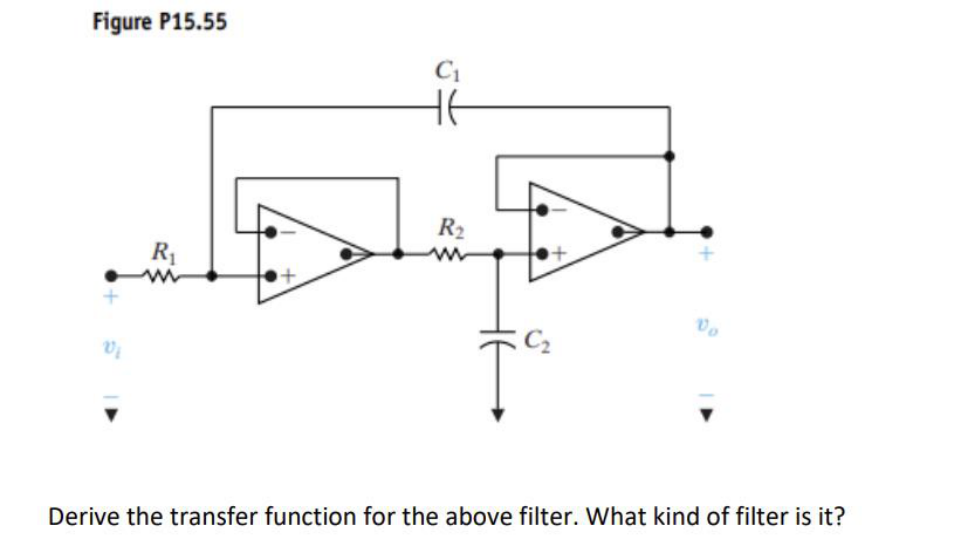
Read the picture:
- Node $A$ (after $R_1$) feeds follower 1, so follower 1 outputs $V_A$.
- Node $B$ is the junction of $R_2$, $C_2$ and follower 2's $+$ input. $R_2$ (in series) and $C_2$ (to ground) form an RC divider: a voltage divider whose bottom part is a capacitor, so $V_B=V_A\frac{1/sC_2}{R_2+1/sC_2}$.
- $C_1$ connects node $A$ to $V_o$.
- $R_2$ and $C_2$ form an RC divider into follower 2, whose output is $V_o$.
Steps
Follower 2: $V_o=V_B$. KCL at B: $\frac{V_B-V_A}{R_2}+V_BsC_2=0\Rightarrow V_A=V_o(1+sR_2C_2)$.
KCL at A (no current into follower 1): $\frac{V_A-V_i}{R_1}+(V_A-V_o)sC_1=0$. Multiply by $R_1$:
$$V_A(1+sR_1C_1)-sR_1C_1V_o=V_i$$ $$V_o\left[(1+sR_2C_2)(1+sR_1C_1)-sR_1C_1\right]=V_i$$ $$V_o\left[s^2R_1R_2C_1C_2+sR_2C_2+1\right]=V_i$$ Divide by $R_1R_2C_1C_2$: $$H(s)=\frac{\frac{1}{C_1C_2R_1R_2}}{s^2+\frac{1}{C_1R_1}s+\frac{1}{C_1C_2R_1R_2}}$$$s\to0$: $H\to1$. $s\to\infty$: $H\to0$. → low-pass (form $k\frac{c}{s^2+bs+c}$ with $k=1$).
Problem 8 (Example 15.6) parallel BRF from Bode plot
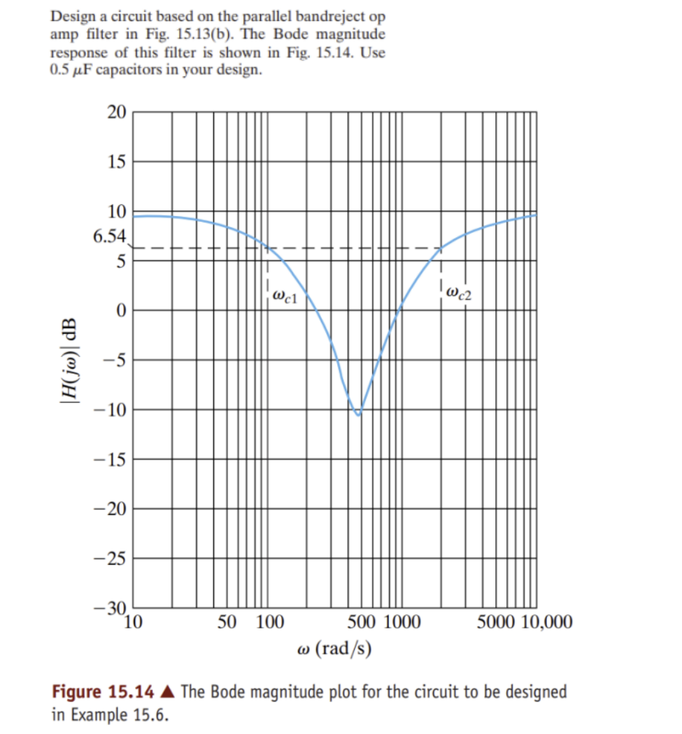
Step 1: Read the plot
- The −3 dB line is at 6.54 dB, so the passband is $6.54+3=9.54$ dB, and $K=10^{9.54/20}=3$.
- The dashed line crosses the curve at $\omega_{c1}=100$ rad/s and $\omega_{c2}=2000$ rad/s.
- $\omega_{c2}/\omega_{c1}=20$, which is broadband, so the parallel design works.
Step 2: Design (C = 0.5 µF everywhere)
- LPF sets the lower cutoff: $R_L=\dfrac{1}{\omega_{c1}C}=\dfrac{1}{100\times0.5\times10^{-6}}=20$ kΩ.
- HPF sets the upper cutoff: $R_H=\dfrac{1}{\omega_{c2}C}=\dfrac{1}{2000\times0.5\times10^{-6}}=1$ kΩ.
- Summing amp gain $R_f/R_i=3$: pick $R_i=1$ kΩ, so $R_f=3$ kΩ.
Problem 9 (P15.6) derive + limits
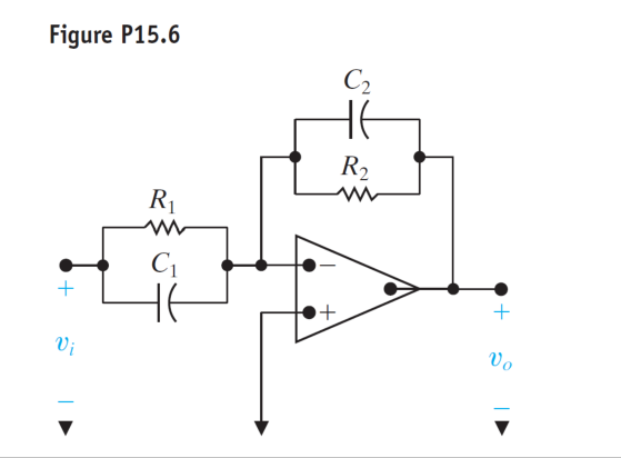
Steps
Inverting amp with $Z_i=R_1\parallel C_1=\frac{R_1}{1+sR_1C_1}$ and $Z_f=R_2\parallel C_2=\frac{R_2}{1+sR_2C_2}$:
$$H(s)=-\frac{Z_f}{Z_i}=-\frac{R_2}{R_1}\cdot\frac{1+sR_1C_1}{1+sR_2C_2}$$ Pull out $R_1C_1$ on top and $R_2C_2$ on the bottom: $\frac{R_2}{R_1}\cdot\frac{R_1C_1}{R_2C_2}=\frac{C_1}{C_2}$, so $$H(s)=-\frac{C_1}{C_2}\cdot\frac{s+\frac{1}{R_1C_1}}{s+\frac{1}{R_2C_2}}$$$\omega\to0$ ($s=0$): $H=-\frac{C_1}{C_2}\cdot\frac{R_2C_2}{R_1C_1}=-\frac{R_2}{R_1}$ (caps open → plain resistor amp).
$\omega\to\infty$: $H\to-\frac{C_1}{C_2}$ (caps dominate; impedance ratio $\frac{1/sC_2}{1/sC_1}$).
Problem 10 (15.30) cascade BPF design
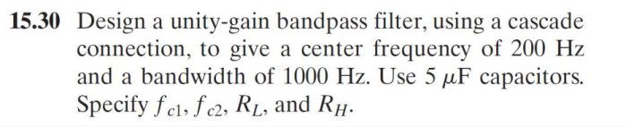
Step 1: Find the cutoffs (in Hz, same formulas work)
$f_{c1}f_{c2}=f_o^2=40{,}000$ and $f_{c2}-f_{c1}=1000$: $$f_{c1}=-500+\sqrt{500^2+200^2}=38.5\text{ Hz},\qquad f_{c2}=500+\sqrt{500^2+200^2}=1038.5\text{ Hz}$$Step 2: Resistors
LPF sets the upper cutoff: $R_L=\dfrac{1}{2\pi f_{c2}C}=\dfrac{1}{2\pi(1038.5)(5\times10^{-6})}=30.65\ \Omega$.
HPF sets the lower cutoff: $R_H=\dfrac{1}{2\pi f_{c1}C}=\dfrac{1}{2\pi(38.52)(5\times10^{-6})}=826.4\ \Omega$.
Unity gain: each stage uses equal resistors, so gain = (−1)(−1) = +1. No third stage needed.
Problem 11 3rd-order Butterworth LPF
Asked: design a LPF with gain 4, $f_c=1$ kHz, roll-off −60 dB/dec, using 10 kΩ resistors. The key says "verify with a simulator", so here is a full design you can build in LTspice.
Step 1: Order
−60 dB/dec = $-20n$, so $n=3$. Butterworth $n=3$: $(s+1)(s^2+s+1)$.Step 2: Prototype stages
Stage 1, $(s+1)$: prototype first-order LPF (Fig 15.1) with $R_1=R_2=1\ \Omega$ and $C=1$ F. Gain $-1$.
Stage 2, $(s^2+1s+1)$, so $b_1=1$: LP cell (Fig 15.21) with $R=1\ \Omega$, $C_1=2/b_1=2$ F, $C_2=1/C_1=0.5$ F. Gain $+1$.
Step 3: Scale
$k_f=2\pi(1000)=6283$. Resistors must be 10 kΩ, so $k_m=10{,}000$. Capacitors divide by $k_mk_f=6.283\times10^7$:
- $1\text{ F}\to15.92$ nF
- $2\text{ F}\to31.83$ nF
- $0.5\text{ F}\to7.96$ nF
Step 4: Gain of 4
Add an inverting amp: $R_i=10$ kΩ, $R_f=40$ kΩ (four 10 kΩ in series). Total gain $=(-1)(+1)(-4)=+4$.14. One-page formula sheet and checklist
- Hz vs rad/s: did I multiply by $2\pi$?
- dB vs linear: did I use $10^{\text{dB}/20}$?
- Is the $s^2$ coefficient 1 before reading $b$ and $c$?
- Cascade BP: LPF = upper cutoff. Parallel BR: LPF = lower cutoff.
- Gain sign: inverting stages give a minus sign. "Gain of 8" usually means $|K|=8$.
- Constraint check: are all resistors ≥ the required minimum (e.g. 1 kΩ)?
- Sanity: plug $s\to0$ and $s\to\infty$ into your $H(s)$. Does the filter type match?
Next: Flashcards → Practice Problems → Practice Quiz